4.1 KiB
Gridfinity Rebuilt in OpenSCAD
A ground-up port (with a few extra features) of the stock gridfinity bins in OpenSCAD. Open to feedback, because I could not feasibly test all combinations of bins. I tried my best to exactly match the original gridfinity dimensions, but some of the geometry is slightly incorrect (mainly fillets). However, I think they are negligible differences, and will not appear in the printed model.
Features
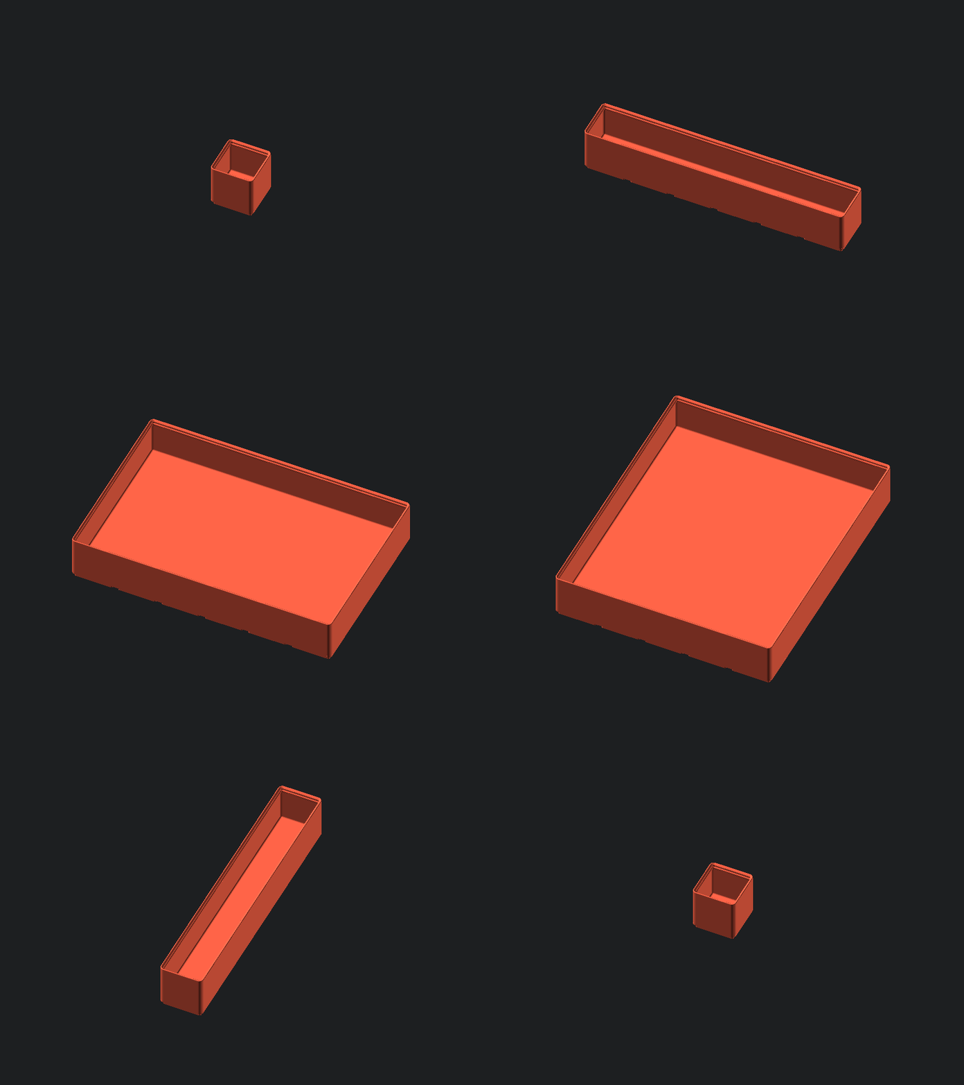
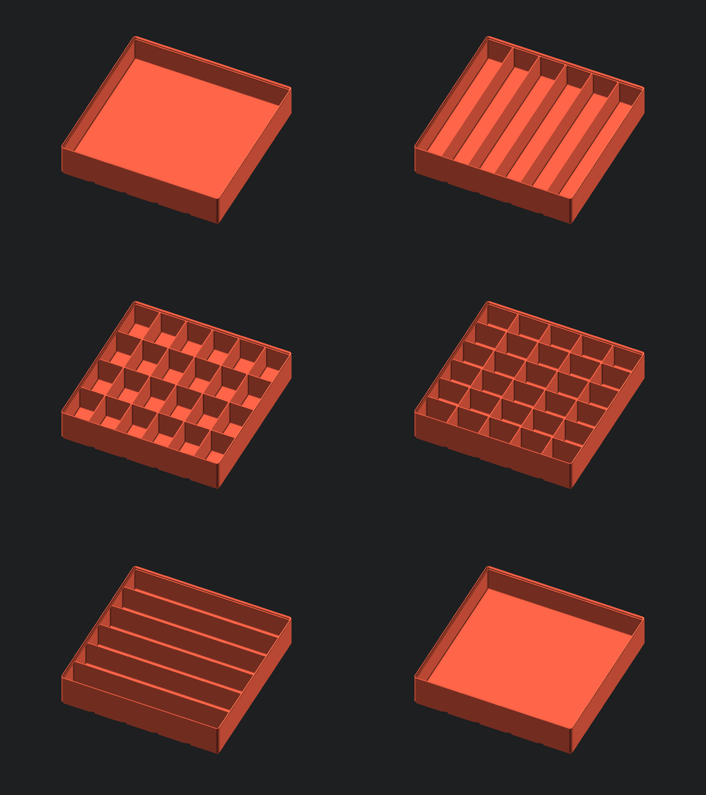
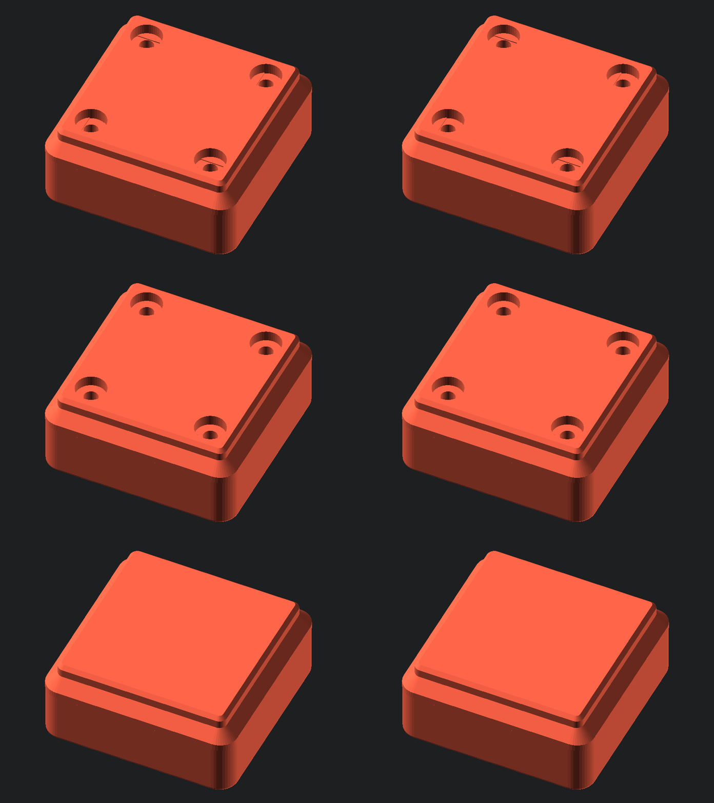
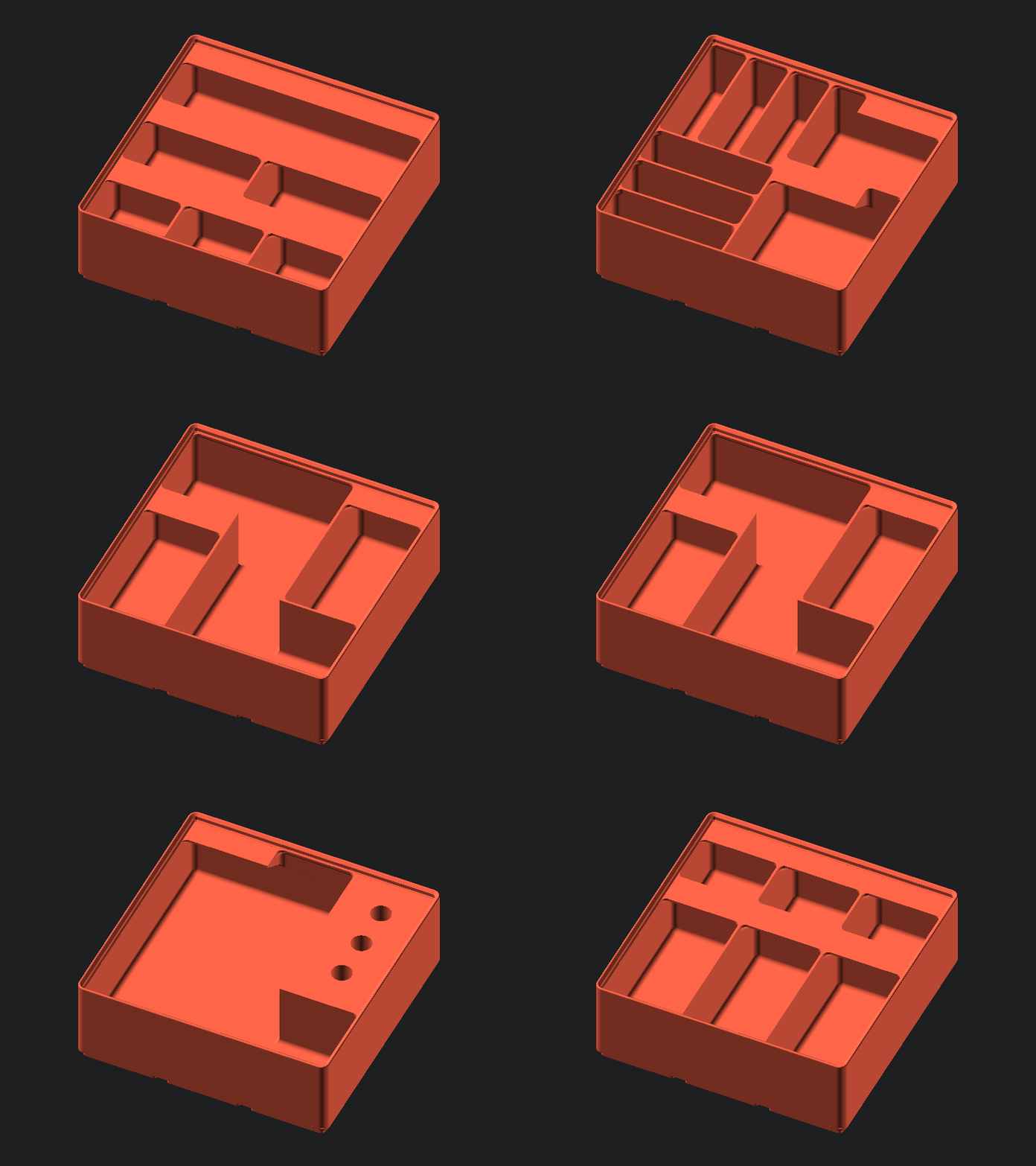
- any size of bin (width/length/height)
- any number of compartments (along both X and Y axis)
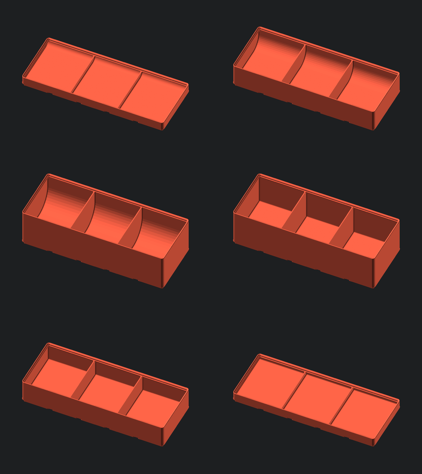
- togglable scoop
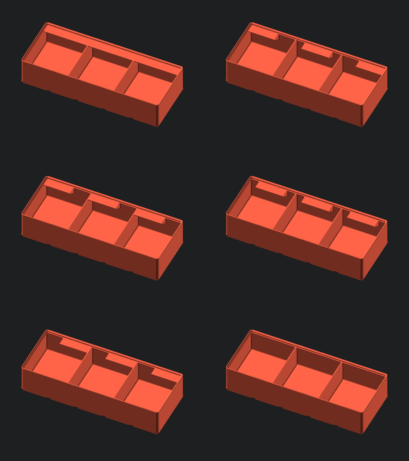
- togglable tabs, split tabs, and tab alignment
- togglable holes (with togglable supportless printing hole structures)
- manual compartment construction (make the most wacky bins imaginable)
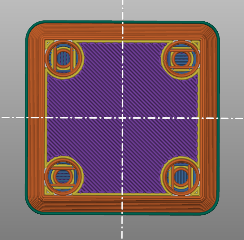
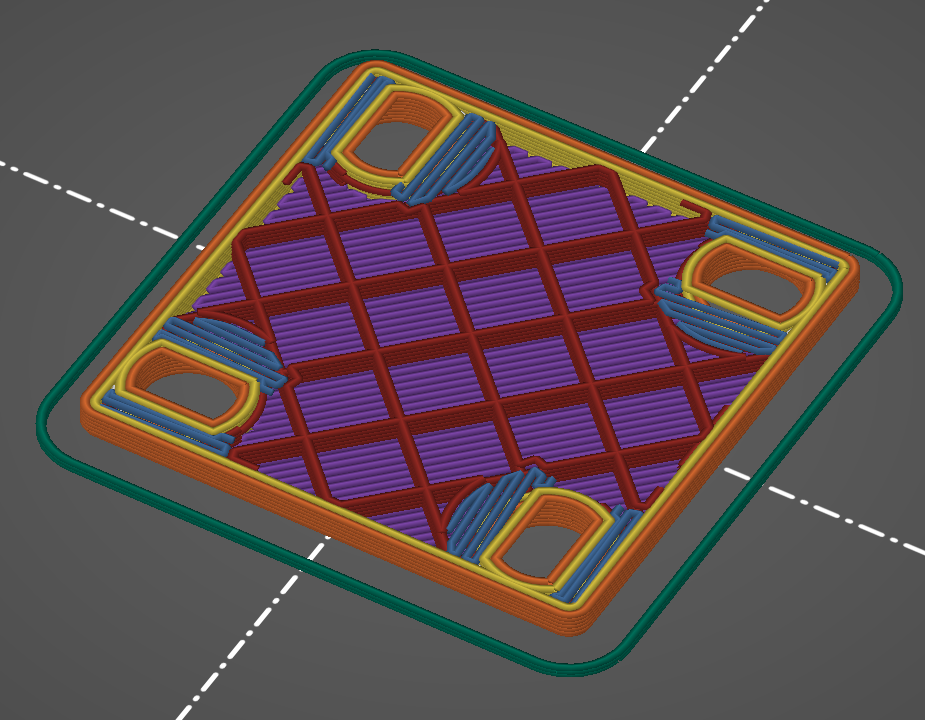
The printable holes allow your slicer to bridge the gap (using the technique shown here) so that supports are not needed.
Instructions
Set the values for gridx, gridy, and gridz global variables as the overall size of the bin. The stock bins have a gridz of either 2, 3, or 6.
The function gridfinityEqual(n_divx, n_divy, style_tab, enable_scoop) is provided to allow an easy way to generate the "traditional" bins. n_divx and n_divy are the number of compartments along X and Y, respectively. style_tab determines how the tabs for labels are generated.
- 0: full tabs across the entire compartment
- 1: automatic tabs, meaning left aligned tabs on the left edge, right aligned tabs on right edge, center tabs otherwise
- 2: left aligned tabs
- 3: center aligned tabs
- 4: right aligned tabs
- 5: no tabs
enable_scoop toggles the scoopy bit on the bottom edge that allows easy removal of items.
If you want to get crazy with it, you can take control of your destiny and manually place the compartments. This can be done using the gridfinityCustom() function, which will cut all child objects into the container. There are various modules that are exposed for this purpose.
cut(x,y,w,h,t,s) will cut a compartment at position (x,y) that has a width w and a height h, along with a tab alignment t and togglable scoop s. The coordinate system for compartments originates at the bottom left corner of the bin, where 1 unit is the length of 1 base (42mm by default). Positive X and positive Y are in the same direction as the global coordinate system. The tab style and scoop only apply to the specific compartment. (x,y,w,h) do not have to be integers. For example, in a 3x3 bin, cut(1,1,1,1,0,true) would cut a 1x1 compartment in the middle of the bin with a full tab and a scoop.
cut_move(x,y,w,h) will move all of its children from the origin to the center of the area that a compartment would normally fill, and cut the block. This allows you to easily make custom cutouts in the bin. For example, in a 3x3 bin, cut_move(0,0,3,1) cylinder(r=10, h=100, center=true); would cut a circular hole of radius 10 in the bottom center block of the bin.
Examples can be found at the end of the file (they were used to generate the last gif).
Recommendations
For best results, use a version of OpenSCAD with the fast-csg feature. As of writing, this feature is only implemented in the development snapshots. To enable the feature, go to Edit > Preferences > Features > fast-csg. On my computer, this sped up rendering from 10 minutes down to a couple of seconds, even for comically large bins.
Enjoy!
